Lean Transformation Lives and Dies With Tools and Dies
When The Wiremold Company tried just-in-time (JIT) production for the first time in the late 1980s, an unexpected increase in die crashes triggered a crash program in maintenance.
“They didn’t really think about the tooling issues,” recalled John Bellemare, tool group leader at the company’s main plant in West Hartford, CT. As a traditional mass producer of wire and cable management systems, the company could use long press runs to offset neglected die maintenance. If a die didn’t work properly, tool and die makers fixed it in the press, which then banged out, say, 100,000 parts. “Then you would take the die and rebuild it because you had a month before you needed it again,” said Bellemare.
Dies were run “until they basically self-destructed,” recalled Jeff Schulze, tool room supervisor. “It was like running your car until it ran out of oil. The repair is going to cost a lot more than an oil change.”
Dies that had been used once a month in the Wiremold® traditional production system were needed once or twice per week or per day in a JIT system that ran small batches of parts in close step with actual customer demand. “You didn’t have time to fix a tool in the press,” said Bellemare. “Dies had to be ready to run every single time they went into the press.” Before long, dies needing work were stacked along walls and aisles in the tool room as the company scrambled to improve tooling reliability. With toolmakers busy repairing and rebuilding dies, they had little time to make new ones. Most new work — along with a lot of repair jobs — was sent to outside vendors, adding to tooling costs and lead times. At any point in time, the company had a standing shop order updated every six months worth hundreds of thousands of dollars for outside tool and die work.
Clearly, a change was needed and it came in 1991 when a new management team took over and began implementing a complete lean transformation grounded in the concept of kaizen – or continuous improvement – that went far beyond earlier JIT efforts. While kaizen workshops on the production floor attacked long lead times, delays, batching, wasted space, and poor material and information flow, kaizens in the tooling department attacked the same problems in tool maintenance, design, and fabrication.
Diagnostic Areas
The first step in improving tool and die operations was establishing a diagnostic area on the shop floor to clean and check tools immediately after each run. The objective was to keep tools well maintained and catch potential problems before they became major repairs. The effort began with one toolmaker dedicated to a busy press. “He had a work area next to the press,” said Bellemare. “Every time a die came off that press, he’d clean it, knock out the slugs, check the product for any quality issues, check the tool for damage or if it needed sharpening, grease it, and put it back on the rack ready to go.”
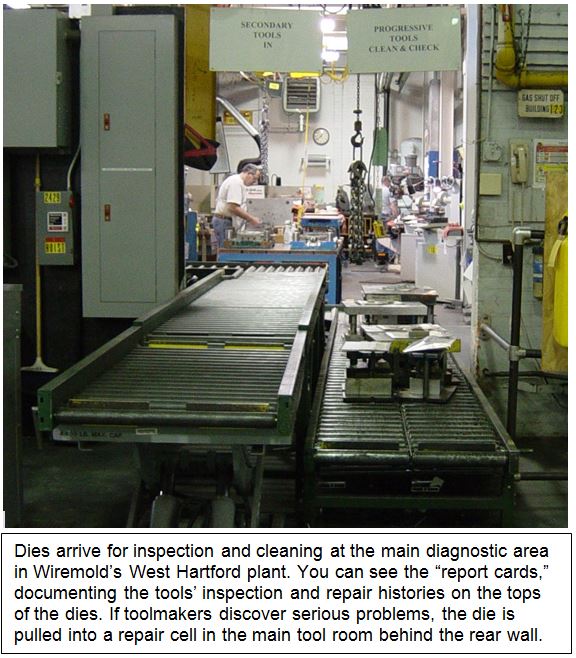
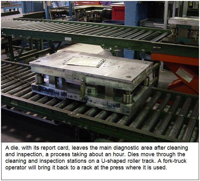
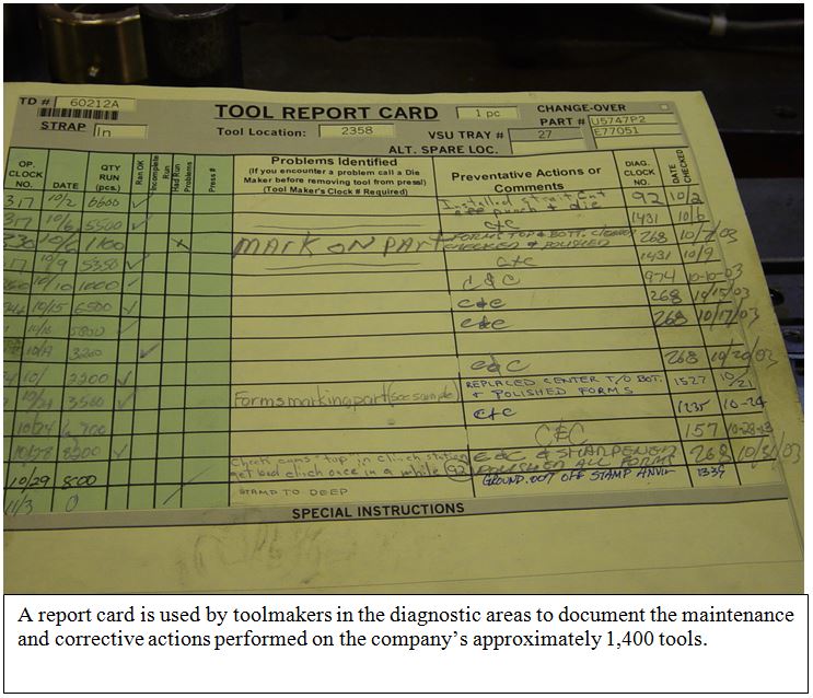
There now are two diagnostic areas, charged with keeping dies in excellent condition, at opposite ends of the shop floor at West Hartford. After every run, the machine operator signals a die handler to retrieve the die just removed from the machine. The handler returns all metal-stamping dies to a diagnostic area along with the last part made, a strip of metal stock from the end of the run, and a plastic envelope bearing the die’s “report card.” This large piece of paper is a concise record of maintenance work and repairs done on the die.
Toolmakers in the diagnostic areas open, clean, and check dies for wear and make minor repairs as needed. They inspect the part and metal stock for any quality issues. If any serious problems are discovered, toolmakers send the tool to a specialized repair cell in the main tool room. A die handler returns refurbished tools to a storage rack near the press that uses it, along with the updated report card. Dies used infrequently are stored on a rack just outside the main diagnostic area.
“If a press makes 10 strokes or 1,000 strokes, the dies must be opened, cleaned, and examined,” explained Tony Laraia, plant manager. “That may sound on the surface like an extravagance, but it puts us in the position of having very, very, high confidence that any tool we take off the rack will run the first time. This is fundamental to Wiremold being able to provide customers with a high level of service on a complex product line with inventory measured in days, not weeks.”
The company’s diligence paid dividends in tool design and fabrication. “We see on a regular basis what works and what doesn’t, what parts break, what parts wear,” said Laraia. This information from diagnostics is communicated daily in emails and conversations between the tool designers and toolmakers. “I think that has had a fundamental effect in the long run of reducing the time it takes to make and maintain tools.” In addition, toolmakers in the tool room and diagnostic areas rotate jobs weekly, which helps disseminate knowledge about best practices. The information sharing is aided by having the Tool Design Department supervise the diagnostic, tool room, and tool design areas.
Tool and Die Cells
Creating the two diagnostic areas in the shop meant dies didn’t pile up for routine servicing in the tool room, freeing capacity to repair dies in-house and build new ones. But bottlenecks in the die building and design process had to be eliminated in order to take full advantage of the new capability.
Like the shop floor, the tool room grouped machines by type for batch-and-queue production, instead of arranging them in processing sequence for continuous flow production. Furthermore, equipment for making die components was located at one end of the tool room and the benches where toolmakers assembled the parts into dies were at the other. The walking and the equipment layout encouraged toolmakers to batch work together for processing, which created bottlenecks.
“We had all our Bridgeports (mills) in one area and all our grinders in another area,” said Schulze. “We had more machines than people but some days you could not get on a grinder and some days you could not get on a Bridgeport. Other days no one was using them at all. That’s when we came up with the cells.”
“The key is to eliminate batching,” said Bellemare. “When you batch die work, you’ll get stuck waiting for a process to finish and you won’t get a steady flow of dies out.”
A series of kaizen events in the tool room moved the equipment from functional areas in to four specialized cells — two “build cells,” a CNC cell, and a cell dedicated to repairing dies. The company approved purchasing a 150-ton hydraulic press in order to test new dies in the tool room, near the build cells. The dedicated trial press eliminated waiting to use shop-floor presses for die tests. “While one build cell is testing a tool in the trial press, the other is building a tool,” explained Bellemare. “This way, tools aren’t waiting to be assembled or to use the trial press. You get a steady flow of work.”
The build cells, including two nearby sub-cells equipped with relatively simple machines for grinding, milling, and drilling, have most of the equipment needed for making die components. The CNC cell, called a technical support cell, makes components that the build cells can’t. It’s equipped with bigger and more sophisticated equipment, including CNC machines, a water jet, and two wire electrical discharge machines.
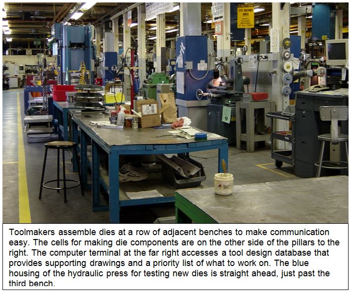
Toolmakers now assemble the components into dies at a row of benches a few steps from the build cells. Clamps, dowels, and other common parts are stored under the benches instead of in cabinets at the back of the tool room or in a crib in the middle of the room (as had been the practice) to minimize walking. Personal tools, once stored on workbenches at one end of the room, are kept in rolling toolboxes and the old workbenches are gone.
“We’re always trying to eliminate the waste of unnecessary movement,” said Bellemare.
“Toolmakers used to stand in line at the crib to sign out tools instead of making details (parts). And we had a full-time crib attendant, too. We got rid of the crib and gave each cell its own cabinet of supplies to use and manage.”
The fourth cell is dedicated to repairs and alterations. It handles repair work that can’t be done in a few hours in the diagnostic areas. “We can’t bottle up the diagnostic areas with big projects because they have to service so many dies every day,” said Schulze.
Concurrent Engineering
At about the same time Wiremold was improving how it maintained and made tools, it was improving how it designed them.
“The conventional design process is carried on serially,” said Laraia. “When the design of the tooling is completed, then the fabrication of components is done and when they are done then the process of fitting them together in a base or frame is carried out, usually with a lot of adjustments and rework.” Typically, the process takes months or longer.
Through scores of kaizen workshops involving tool designers and toolmakers, Wiremold overlapped the design and fabrication processes. “You have to think of it as a flow, not a serial, segmented process,” said Laraia. “While certain elements of the design are still being conceived, other elements are being built and fitted into the frame. By the end of the design process, we have a lot of the fabrication done.”
“On several occasions, we’ve designed and built dies in less than a week,” said Schulze. “We don’t waste a lot of time measuring details because quality is built into the process,” Assembling the tool as parts are made is the best quality check point you can have for fit, form, and function. Putting the part into the tool tests everything from the quality of the craftsman making the part, to the quality of the design or draftsmanship.”
Engineering and building tools concurrently begins in product development. Bellemare attends product design meetings along with managers from other functions to evaluate designs for manufacturability and to estimate costs. “We all want to be on the same page before sending a product out to the shop floor,” he said. His cost estimates, based on the types and quantities of tools required for the project, go to a management team that decides if the project proceeds. This allows the tool department to write one shop order for the entire project, instead of obtaining separate orders and approvals for each tool.
Besides the cross-functional team meetings, Wiremold adopted information technology to support parallel design and fabrication. A product engineer finishing a design fills out an online product release form that contains information needed by tool designers, such as the part number, product drawing, and materials to use. With a mouse click, the electronic package is captured by the tool design database and an email is sent to Bellemare that the product design is ready. “We used to run around chasing down this information,” he said.
Locating the part design drawing in the database, he uses it and accompanying information to determine the manufacturing process and the types of tools. With a mouse click, he sends the information to the assigned tool designers. “Now they have all the information from me and the product engineer so they don’t have to chase after information,” said Bellemare.
Usually, two designers at a time work on a tool in a 3D computer-aided design (CAD) system. Wiremold tool designers have developed macroinstructions and special sub-programs to standardize and streamline the design of certain tool features. For example, a macro lets designers automatically add the correct hole locations and dimensions to a steel block instead of separately locating each hole and entering the dimensions. A sub-program written in-house automatically applies standards developed for different press types. For example, at the start of the design process, a tool designer types into the CAD system the press number where the die will run. The program will let designers use only the standardized settings for such functions as shut height, feed path, clamping arrangement, block thickness, etc. And instead of designing tools completely from scratch every time, designers copy “clone files” of standardized subassemblies into the new design, which streamlines the process and prevents mistakes.
“You can build a product out of standard components, but you can also build a product out of standard process steps,” said Laraia. “What we’ve come up with are standardized process steps that we know work well. They allow us to modularize the design and modularize the process steps in tool making. They’ve helped us take a tremendous amount of time out of the process and made the process more dependable.”
“We can have the die half built when we’re still doing the design,” said Schulze.
When designers are satisfied with a section of a large die, they transfer the file to a draftsman to finish detailing the component parts. When the detailing is finished, the draftsman electronically scans the drawing into the tooling database, which creates a bill of materials (BOM) for the die and a bar-coded traveler identifying the components, their dimensions, the die number, and the sequence of fabrication steps. Some smaller dies are often fully designed before they are released. Larger dies are released in stages.
When toolmakers check computer monitors in the morning, the database lists the released jobs in order of priority as set by Bellemare. The priority list prevents one cell or process from being overwhelmed with work. Group leaders print the travelers and the BOMs from the database. The BOMs, automatically sorted by vendor, are faxed to vendors as material orders. Before the database was developed, group leaders wrote out orders after reviewing the parts lists for dies and would sometimes transfer the information incorrectly.
One-Tool Flow
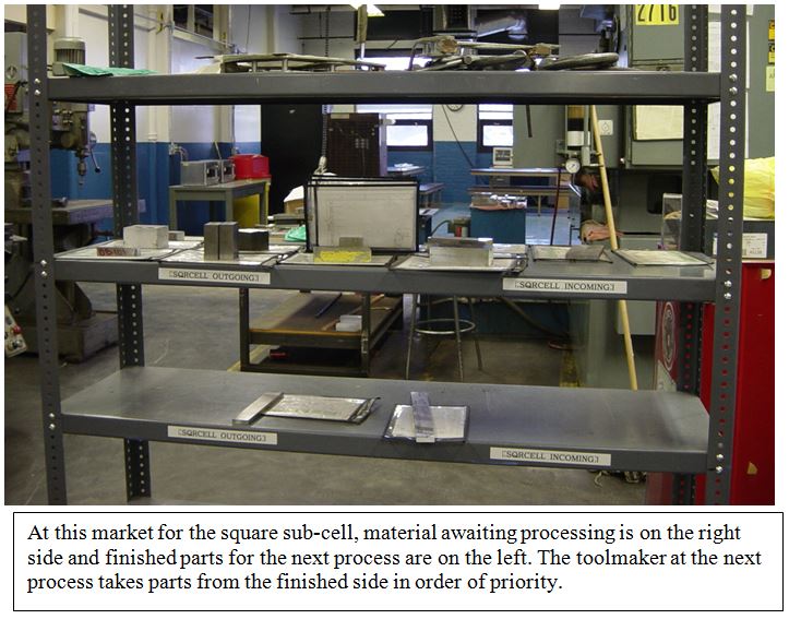
Vendors deliver material to the tool room’s receiving dock, where it is matched with the bar-coded travelers and placed on one side of a rack that serves as the incoming raw materials market for the first fabrication process, called the square sub-cell. A computer monitor in the cell displays the priority list of jobs for the toolmaker, who uses a large Blanchard grinder or a milling center to shape steel blocks to the precise dimensions. Because this process is the first stop for virtually all parts, a toolmaker is dedicated to this sub-cell. Toolmakers are assigned to the four cells, but rotate weekly among the various jobs within the cell, such as assembly, drilling, milling, etc.
When the part is completed, the square sub-cell operator puts it on the other side of the rack, which is the finished parts market. The next stop for most parts is the adjacent milling/drilling sub-cell. A toolmaker working there takes a block from the rack, based on the computerized priority list, adds holes, chamfers, and other features, then puts the block on the “finished” side of a rack for the next process. A blueprint accompanying the part illustrates the process sequence as well as dimensions and other key information.
As a part make its way through the various processes, toolmakers scan the bar code on the traveler. The information captured in the database shows group leaders where every part is, how long it’s been at that process, and the total hours spent on a job, said Schulze.
The system of supermarkets and prioritizing work — combined with the streamlined tool design process — creates what the company calls “one tool flow,” said Bellemare. “The philosophy is based on the idea that no tool is of any use until it is complete.” With three to four tools in process at any given time, excess work-in-process (WIP) could overwhelm resources and stretch out lead times. “Processes like tryouts would not take place for months and then happen all at once bringing everything else to a halt,” he explained. “When tools are produced in one-tool-flow, the demand on resources is more level. Processes and flow are more stable, causing fewer interruptions in day-to-day activities.”
The streamlined process is a big reason why the number of new tools made annually increased from two to three at the start of the lean conversion in the early 1990s to more than 50 today, while the number of toolmakers dropped from about 60 to 43. As in the shop, no one was laid off because of the transformation; headcount dropped through attrition.
Across an aisle from the tool and die cells, a bulletin board tracks performance on tooling department objectives in relation to the key company metrics of 100 percent customer service, 50 percent annual reduction in defects, 50 percent new product introductions, 20 percent annual productivity gains, at least 20 inventory turns, and maintaining a clean workplace that supports visual management. The board also tracks department safety, absenteeism, service calls per tool per week, and upcoming improvement projects in priority order.
The Wiremold Company continues to look for ways to improve the tool design, maintenance, and fabrication processes, despite the very tangible benefits from past efforts. “We’ve taken time out of the process, streamlined the process, and made it more reliable,” said Laraia. “This makes us more responsive to customers in terms of product innovation and reducing product costs by improving tooling. But this has been a long-term continuous improvement process, the result of dozens and dozens and dozens of kaizens that went on and continue to go one. It’s not a process we’ll ever be finished with.”
Tool Room Performance Box Score
|
|
Before Lean |
After Lean |
|
No. of toolmakers |
60 |
43 |
|
Crib attendants |
1 |
0 |
|
Tool designers |
8 |
6 |
|
Weekly OT hrs./toolmaker |
Mandatory 15 hrs. |
0 |
For more information
The Wiremold Company is part of Legrand North America, headquartered in West Hartford, Conn. Legrand is a leader in products and systems for electrical installations and information networks in residential housing, commercial buildings, and industry. The Legrand group has some 60 units worldwide and sells in more than 160 countries.
Workshops and Workbooks
The Lean Enterprise Institute (LEI) runs monthly regional workshops on basic and more advanced lean tools. You can read complete descriptions of workshop content with the latest dates and locations at LEI Training. LEI workbooks and training materials – all designed to de-mystify what a sensei does – show you what steps to take on Monday morning to implement lean concepts. Visit the LEI product catalog to see the resources available for supporting lean transformations.
Continuous Flow
Producing and moving one item at a time (or a small and consistent batch of items) through a series of processing steps as continuously as possible, with each step making just what is requested by the next step. Continuous flow can be achieved in a number of ways, ranging from moving assembly lines to manual cells. It is also called one-piece flow, single-piece flow, and make one, move one. (Adapted from the Lean Lexicon)
Just-in-Time (JIT) Production
A system of production that makes and delivers just what is needed, just when it is needed, and just in the amount needed. JIT and jidoka are the two pillars of the Toyota Production System. JIT relies on heijunka as a foundation and is comprised of three operating elements: the pull system, takt time, and continuous flow. JIT aims for the total elimination of all waste to achieve the best possible quality, lowest possible cost and use of resources, and the shortest possible production and delivery lead times. Although simple in principle, JIT demands discipline for effective implementation. (Adapted from the Lean Lexicon)
A group kaizen activity, commonly lasting five days, in which a team identifies and implements a significant improvement in a process. A common example is creating a continuous flow cell within a week. To do this a kaizen team — including staff experts and consultants as well as operators and line managers — analyzes, implements, tests, and standardizes a new cell. Participants first learn continuous flow principles and then go to the shop floor to assess actual conditions and plan the cell. Machines are then moved and the new cell is tested. After improvements, the process is standardized and the kaizen team reports out to senior management. (Adapted from the Lean Lexicon)


